Commercial air compressors are vital for numerous industries, but like any machinery, they can encounter problems. Diagnosing air compressor issues promptly is crucial for maintaining operational efficiency and preventing costly downtime. This guide, brought to you by the experts at xentrydiagnosis.store, will walk you through common air compressor problems, enabling you to effectively diagnose the root cause and explore potential solutions.
Expert Tip: Safety first! Before undertaking any diagnostic work on your air compressor, always disconnect it from its power supply and adhere to lockout/tagout procedures. Consult your user manual for specific safety guidelines, and if you’re unsure about any step, always seek professional assistance.
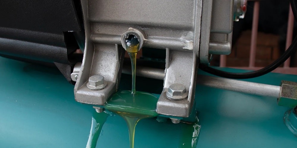
1. Identifying Compressor Oil Leaks and Consumption Issues
Proper lubrication is the lifeblood of oil-flooded rotary screw and reciprocating air compressors. Insufficient oil levels, incorrect oil viscosity, or a dry oil sump can quickly lead to significant damage. Recognizing oil-related problems early is key to Air Compressor Diagnosis and preventing major repairs.
An oil leak may manifest as a visible puddle beneath the compressor, or you might notice that the oil level is decreasing faster than expected. Common diagnostic points for oil leaks include:
- Seal and Gasket Degradation: Over time, the constant exposure to heat, pressure, and vibration causes seals and gaskets to wear down and lose their integrity, resulting in oil leaks. In piston compressors, improperly installed piston rings can also contribute to oil leakage.
- Damage to Oil Lines and Reservoirs: Oil lines and reservoirs can develop cracks, punctures, or corrosion due to aging or physical impact, leading to leaks.
- Loose Fittings and Connectors: The vibrations generated during compressor operation can loosen fittings and connectors, creating pathways for oil to escape.
- Oil Filter Malfunctions: A clogged or damaged oil filter can cause pressure imbalances, leading to leaks and hindering proper oil flow, which compromises lubrication.
- Overfilled Oil Sump Issues: Adding too much oil to the sump can create excessive pressure, forcing oil past seals or vents and increasing the risk of oil contamination in the compressed air system.
Diagnostic Steps:
- Visual Inspection of Seals, Gaskets, and Connections: Carefully examine all seals, gaskets, fittings, connectors, and oil lines for any signs of wear, cracks, or physical damage. Note any loose connections or points of oil accumulation.
- Oil and Filter Condition Assessment: Check the oil level and condition. Is it low? Does it appear dirty or contaminated? When was the oil and filter last changed? These observations can indicate potential leak points or lubrication issues.
- Leak Detection Techniques: Use a clean cloth to wipe around potential leak areas (seals, fittings). Check the cloth for fresh oil. For more precise diagnosis, consider using leak detection dyes that can be added to the oil.
- Pressure Testing (Professional): In some cases, a professional technician may perform pressure testing to pinpoint leaks within the system.
| Table: Best Practices for Oil Level and Quality Maintenance |
|---|
| 1. Routine Oil Level Checks |
| 2. Adherence to Recommended Oil Type |
| 3. Scheduled Oil Replacement |
| 4. Oil Quality Monitoring |
| 5. Oil Sump Cleaning Protocol |
| 6. Proactive Leak Inspections |
2. Diagnosing Air Compressor Overheating Problems
Image of an air compressor overheating, possibly with heat waves visualized or a warning indicator
Air compressor overheating is a serious issue that can lead to system breakdowns, reduced efficiency, and costly repairs. Accurate diagnosis of overheating is crucial to prevent long-term damage. Several factors can contribute to this problem:
- Insufficient Lubrication: Inadequate or degraded oil reduces lubrication, increasing friction and heat generation within moving components.
- Inadequate Ventilation: Poor airflow around the compressor allows heat to build up, causing components to overheat.
- Elevated Ambient Temperatures: Operating the compressor in excessively hot environments can overwhelm its cooling capabilities.
- Clogged Filters and Hoses: Blockages in filters or hoses restrict airflow, forcing the compressor to work harder and generate more heat.
- Cooling System Malfunctions: Issues with the air compressor cooling system, such as malfunctioning fans, dirty cooling fins, or low coolant levels in liquid-cooled systems, impair heat dissipation.
- Duty Cycle Overload: Exceeding the compressor’s recommended duty cycle by running it too frequently without adequate rest periods can cause overheating, especially in systems not designed for continuous operation.
Diagnostic Steps:
- Temperature Monitoring: Use an infrared thermometer to check the temperature of the compressor motor, air end, and discharge lines. Compare these readings to the manufacturer’s specifications or typical operating temperatures.
- Ventilation Assessment: Ensure the compressor is located in a well-ventilated area with sufficient airflow. Check for obstructions blocking vents or airflow around the unit.
- Cooling System Inspection:
- Air-cooled systems: Inspect cooling fins for dirt and debris. Ensure cooling fans are operational and blowing air in the correct direction.
- Liquid-cooled systems: Check coolant levels and inspect for leaks in hoses or the radiator. Verify the coolant pump is functioning.
- Filter and Hose Examination: Inspect air intake filters and hoses for blockages or restrictions. Dirty filters significantly reduce airflow and can contribute to overheating.
- Duty Cycle Review: Assess the compressor’s operating schedule. Is it running within the recommended duty cycle? Overuse can lead to heat buildup.
- Oil Condition Check: As with oil leaks, check the oil level and condition. Degraded oil can reduce cooling capacity and increase friction.
3. Diagnosing Excessive Air Compressor Noise
Excessive noise from an air compressor is often an early warning sign of a developing problem. While commercial compressors naturally produce some noise, significant increases or unusual sounds warrant immediate diagnosis. Common causes of increased noise include:
- Loose, Worn, or Misaligned Components: Bolts, belts, pulleys, and internal mechanisms can loosen or wear down over time, creating rattling, clanking, or squealing sounds. Misalignment can also induce unusual vibrations and noises.
- Improper Mounting and Vibration: An improperly mounted compressor can vibrate excessively against its base or surrounding structures, amplifying noise levels.
- Inadequate Lubrication and Friction: Insufficient lubrication leads to increased friction between moving parts, often resulting in squealing, screeching, or grinding noises.
- Internal Component Damage: Misaligned screws in rotary screw compressors can produce a high-pitched whine or grinding sound. Damaged pistons in reciprocating compressors can cause knocking or clanking noises.
- Motor Bearing Issues: Worn or poorly lubricated motor bearings often generate whining or grinding sounds, and if left unaddressed, can lead to motor failure.
Diagnostic Steps:
- Noise Isolation and Type Identification: Pinpoint the location of the noise and describe its characteristics (rattling, squealing, grinding, knocking, etc.). This helps narrow down potential causes.
- Component Tightness Check: Inspect and tighten all accessible bolts, belts, pulleys, and the belt guard. Loose components are a common source of noise.
- Mounting and Vibration Pad Inspection: Verify that the compressor is securely mounted and that vibration-damping pads are correctly installed and in good condition.
- Lubrication System Assessment: Ensure the compressor is properly lubricated with the recommended oil type and quantity. Check for signs of lubrication failure around bearings and moving parts.
- Motor Bearing Noise Evaluation: Carefully listen to the motor area for whining or grinding sounds that could indicate bearing problems. (Note: Rotary screw compressor bearing replacement should be done by a professional).
- Professional Internal Inspection (if necessary): If external checks don’t identify the noise source, internal issues like misaligned screws or piston damage may require professional inspection and diagnosis.
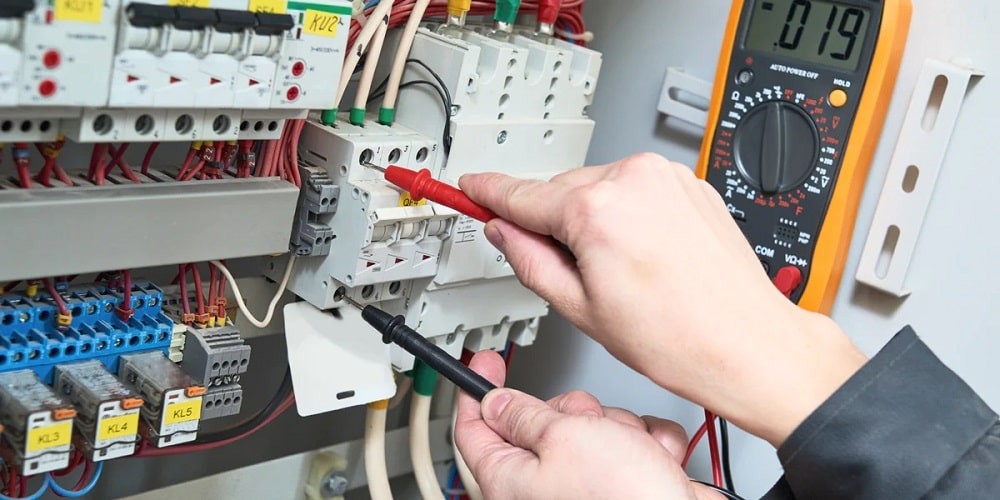
4. Diagnosing Repeated Air Compressor Fuse Blowouts
Repeatedly blown fuses in an air compressor circuit indicate an electrical overload or fault. Diagnosing the cause of these fuse failures is essential for electrical safety and compressor functionality. Potential causes include:
- Circuit Overload: Sharing a circuit with other high-power devices can overload the circuit, especially if the combined amperage draw exceeds the circuit’s rating.
- Motor Faults or Deterioration: A failing or aging motor may draw excessive current, exceeding the fuse rating and causing it to blow.
- Electrical Wiring Problems: Damaged wiring or loose connections within the compressor or circuit can create short circuits or increased resistance, leading to fuse failure.
- Compressor Overheating and Electrical Strain: Excessive heat can put strain on the motor and electrical system, causing the compressor to draw more current.
- Operating Beyond Rated PSI: Running the compressor at pressures exceeding its design limits forces the motor to work harder, increasing power consumption and the risk of electrical overloads.
Diagnostic Steps:
- Circuit Load Assessment: Determine if the air compressor shares a circuit with other high-power equipment. Calculate the total amperage draw on the circuit and compare it to the circuit breaker or fuse rating.
- Motor Amperage Testing: Use a multimeter to measure the current draw of the compressor motor during startup and normal operation. Compare these readings to the motor’s nameplate amperage rating. Elevated readings indicate a potential motor problem.
- Wiring and Connection Inspection: Visually inspect all electrical wiring and connections within the compressor and in the power supply circuit for signs of damage, fraying, or looseness.
- Overheating Checks: As discussed earlier, diagnose and address any overheating issues, as these can contribute to electrical strain.
- PSI Rating Verification: Ensure the compressor is being operated within its recommended pressure (PSI) limits. Over-pressurization can strain the motor and electrical components.
- Fuse Type and Rating Confirmation: Verify that the correct type and amperage rating fuse is being used for the compressor circuit. Using an incorrect fuse can lead to nuisance tripping or, conversely, inadequate protection.
5. Diagnosing Air Compressor Start-Up Failures
If an air compressor fails to start, diagnosing the issue requires differentiating between power supply problems and internal compressor malfunctions.
If the compressor hums but fails to start, it indicates power is reaching the motor, but there’s a mechanical or electrical issue preventing rotation. Common causes for humming but no start include:
- Capacitor Failure: Failed start or run capacitors in the motor can prevent it from generating sufficient torque to initiate rotation.
- Damaged Motor Windings: Worn or damaged motor windings can disrupt the motor’s magnetic field, reducing its starting capability.
- Overload Protection Triggered: Overheating or overcurrent conditions can activate the compressor’s overload protection, preventing start-up.
- Check Valve Malfunction: A faulty tank check valve can allow compressed air to backflow into the compressor, creating back pressure that prevents starting.
- Intake Filter Blockage: Obstructed intake filters restrict airflow, making it harder for the compressor to build initial pressure and start.
- Air End Bearing Seizure: Seized or worn air end bearings create excessive mechanical resistance, preventing the motor from turning the compressor components.
If the compressor is completely unresponsive (no humming or any sound), possible issues include:
- Power Supply Interruption: No power reaching the compressor due to a tripped circuit breaker, disconnected power cord, or blown fuse in the main electrical panel.
- Starter Circuit Problems: A faulty starter may fail to engage and deliver power to the motor.
- Low Cut-In Pressure Setting: If the compressor’s cut-in pressure setting is set too low, it won’t initiate a start cycle when tank pressure drops.
- Internal Motor Damage: Internal motor failures like a seized rotor or electrical shorts can completely prevent starting.
- Faulty Start Switch or Control Board: Malfunctioning electrical components responsible for initiating the compressor start sequence can cause failure.
Diagnostic Steps:
- Power Connection Verification: Check that the power cord is securely plugged in, the power switch is in the “on” position, and circuit breakers are not tripped in the main panel. Inspect and replace any blown fuses in the main panel or compressor disconnect.
- Cut-In Pressure Setting Check: Verify that the compressor’s cut-in pressure setting is appropriately set to trigger a start cycle when needed.
- Check Valve and Filter Inspection: Examine the tank check valve for proper function (no backflow). Inspect intake filters for blockages and replace if dirty.
- Starter and Capacitor Testing: (Requires electrical knowledge) Inspect the starter for any visible faults. Test capacitors using a multimeter to check for capacitance and shorts. Replace failed capacitors.
- Motor Evaluation (Humming but no start): If the motor hums but doesn’t start, suspect internal motor issues. Professional motor diagnostics or replacement may be needed.
- Professional Assistance (Unresponsive Compressor): If basic checks don’t resolve the issue, especially with a completely unresponsive compressor, seek professional help for electrical system diagnosis and potential internal motor problems.
6. Diagnosing Air Compressor Run-On Issues (Failure to Stop)
An air compressor that continues to run and fails to shut off at its set pressure poses significant safety hazards, primarily due to the risk of over-pressurization. Over-pressurization can damage the compressor, tank, and connected equipment, and in extreme cases, lead to tank rupture. Prompt diagnosis is critical. Potential causes include:
- Faulty Pressure Relief Valve: The pressure relief valve is a critical safety device designed to vent excess pressure if the tank exceeds safe limits. If it’s stuck closed, damaged, or clogged, it won’t relieve pressure, and the compressor may continue running.
- Defective Power Switch: A malfunctioning power switch may fail to interrupt power to the compressor motor when the cut-off pressure is reached.
- Malfunctioning Pressure Switch: The pressure switch monitors tank pressure and signals the compressor to stop at the cut-off point. A defective pressure switch may fail to register that the cut-off pressure has been reached, allowing continuous operation.
Diagnostic Steps:
- Immediate Power Disconnection: If the compressor fails to stop at its cut-off pressure, immediately turn off the power supply to prevent over-pressurization.
- Pressure Relief Valve Inspection and Testing: Visually inspect the pressure relief valve for any obstructions, corrosion, or mechanical damage. Manually test the valve to ensure it can be opened and releases pressure. Replace the valve if it’s faulty.
- Pressure Switch Testing: (Requires electrical knowledge) Use a multimeter to test the pressure switch for continuity and proper operation at the cut-off pressure setting. Replace the pressure switch if it’s defective.
- Power Switch Examination: Inspect the power switch for physical damage, loose connections, or signs of malfunction. Replace the switch if it’s not operating correctly.
- PSI Setting Verification: Double-check the pressure switch’s cut-off pressure setting to ensure it’s correctly set for the compressor’s safe operating pressure range.
7. Diagnosing Excessive Power Consumption in Air Compressors
Industrial air compressors are substantial energy consumers. Increased power consumption often indicates inefficiencies or equipment problems that can signal impending failures. Diagnosing the cause of excessive power use is crucial for cost savings and preventative maintenance. Common causes include:
- Lack of Regular Maintenance: Neglecting routine maintenance tasks like cleaning, lubrication, filter replacements, and condensate draining reduces compressor efficiency and increases energy consumption.
- Compressed Air Leaks: Air leaks throughout the compressed air system force the compressor to work harder and longer to maintain pressure, wasting significant energy.
- Operating at Unnecessarily High Pressure: Running the compressor at pressures higher than required for the application wastes energy.
- Aging or Deteriorating Motor: Over time, electric motors lose efficiency due to wear and tear, requiring more power to perform the same work.
Diagnostic Steps:
- Maintenance History Review: Check the compressor’s maintenance records. Is routine maintenance being performed on schedule? Lack of maintenance is a primary contributor to inefficiency.
- Leak Detection Survey: Conduct a thorough air leak survey of the entire compressed air system, including compressor components, distribution piping, hoses, and connections. Repair all identified leaks. (Ultrasonic leak detectors are effective for this).
- Pressure Optimization Assessment: Evaluate the operating pressure of the compressor. Is it set higher than necessary for the intended applications? Reduce pressure to the lowest acceptable level to save energy.
- Motor Efficiency Evaluation: If power consumption remains high after addressing maintenance and leaks, consider evaluating the motor’s efficiency. An aging motor may need replacement with a more energy-efficient model.
- Energy Audit (Professional): For persistent high energy consumption, consider a professional compressed air system energy audit. Auditors can identify inefficiencies and recommend targeted improvements.
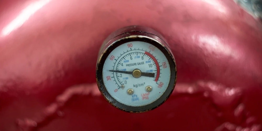
8. Diagnosing Insufficient Air Pressure Generation
If an air compressor is not generating enough pressure, diagnosis must consider both compressor-related issues and problems within the compressed air distribution system. The problem could be within the compressor itself, the distribution lines, an undersized system, or incorrect pressure settings. Common causes include:
- Distribution System Losses: If the compressor generates adequate pressure, but pressure is low at the point of use, the issue is likely in the distribution system. Common culprits are air leaks, clogged inline filters, and excessive use of quick couplers and hoses, all causing pressure drops.
- Air End Malfunctions: Internal compressor problems, such as leaks between high- and low-pressure pistons (reciprocating compressors), rotor misalignment (rotary screw compressors), or leaky seals and gaskets in the air end, can reduce pressure output.
- Intake or Discharge Valve Problems: A clogged air intake filter or a malfunctioning discharge valve or inlet valve can restrict airflow and reduce pressure.
- Undersized Compressor: If the air demand (CFM) of the application exceeds the compressor’s capacity, the system will struggle to maintain adequate pressure.
Diagnostic Steps:
- Distribution System Pressure Drop Analysis: Use pressure gauges to measure pressure at the compressor outlet and at various points of use in the distribution system. Significant pressure drops indicate problems in the distribution network.
- Leak Detection in Distribution: Conduct a thorough air leak survey of the distribution system, as leaks are a primary cause of pressure loss.
- Inline Filter Inspection: Check and replace clogged inline filters in the distribution system.
- Quick Coupler and Hose Assessment: Minimize the use of quick couplers and excessive hose lengths, as these can restrict airflow and reduce pressure.
- Compressor PSI Setting Verification: Ensure the pressure regulator on the compressor is correctly set and functioning properly. Replace the regulator if faulty.
- Intake and Discharge Component Inspection: Check air intake filters for blockages and replace if needed. Inspect discharge valves and inlet valves for proper operation and freedom from blockage.
- Compressor Sizing Evaluation: Determine if the compressor is adequately sized for the application’s air demand (CFM and PSI requirements). An undersized compressor will not be able to maintain pressure under load.
- Professional Air End Examination (if needed): If distribution system issues are ruled out, and the compressor itself is suspected, professional inspection of the air end is needed to diagnose internal problems like rotor misalignment or piston leaks.
9. Diagnosing Excessive Oil Carryover in Discharge Air
Oil carryover, where lubricating oil escapes into the compressed air, is a common problem in oil-lubricated compressors. It can damage downstream equipment, contaminate processes, and increase maintenance costs. Diagnosis is key to preventing these issues. Common causes include:
- Oil Separator Malfunction: A faulty, saturated, or incorrectly installed oil separator (in screw compressors) will fail to effectively remove oil from the discharge air.
- Overfilled Oil Sump: Excess oil in the sump, whether due to overfilling during maintenance or a system malfunction, increases the likelihood of oil carryover.
- Blocked Oil Return Line (Screw Compressors): In screw compressors, a blockage in the oil return line prevents oil from returning to the sump, forcing it into the discharge air stream.
- Incorrect Oil Viscosity: Using oil with the wrong viscosity or operating in extreme temperatures can affect oil separation and increase carryover.
Diagnostic Steps:
- Oil Level and Condition Check: Verify that the oil level in the sump is within the recommended range (not overfilled). Assess the oil’s condition – is it degraded or contaminated? Drain excess oil and replace degraded oil.
- Oil Separator Inspection and Testing (Screw Compressors): Inspect the oil separator for proper installation and signs of damage or saturation. In some cases, pressure differential testing across the separator can assess its performance. Replacement is often necessary for saturated or faulty separators.
- Oil Return Line Examination (Screw Compressors): Inspect the oil return line for blockages caused by sludge, rust, or debris. Clean the line thoroughly or replace it if necessary to restore proper oil return.
- Oil Viscosity Verification: Confirm that the compressor is using the correct oil viscosity grade as recommended by the manufacturer, especially if operating in extreme temperature conditions.
- Downstream Contamination Checks: Inspect downstream air lines, filters, and equipment for signs of oil contamination (oily residue). This confirms oil carryover is occurring.
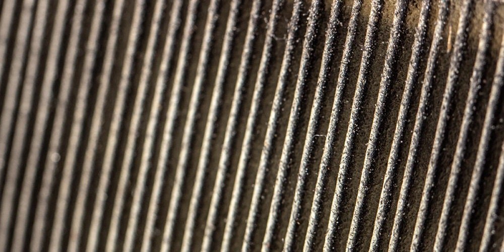
10. Diagnosing Air Compressor Intake Obstructions
A blocked or obstructed air compressor intake restricts airflow, leading to reduced air pressure, increased energy consumption, and potential overheating. Diagnosing intake obstructions is typically straightforward. Common causes include:
- Clogged or Dirty Air Filters: Neglecting regular air filter replacement allows dust, dirt, and debris to accumulate, severely restricting airflow.
- Faulty Inlet Valve or Intake Components: A malfunctioning inlet valve, intake valve, or air intake pump (in some compressor designs) can prevent the compressor from drawing in air effectively.
Diagnostic Steps:
- Air Filter Visual Inspection: Visually inspect the air intake filter(s). Are they visibly dirty, clogged with dust, or damaged? Replace dirty filters immediately.
- Filter Replacement Schedule Review: Check the compressor’s maintenance schedule. Are air filters being replaced at the recommended intervals?
- Inlet Valve and Intake Component Examination: Inspect the inlet valve and other intake components for any visible damage, blockage, or malfunction. For piston compressors, check the valve plate for damage. Professional repair or replacement may be needed for faulty valves.
- Airflow Test (if necessary): In more complex cases, airflow measurement at the intake can quantify the extent of any obstruction.
Additional Air Compressor Diagnosis Considerations
Beyond these common issues, other problems can arise in both piston and rotary screw compressors and within the broader compressed air system.
Diagnosing Air Leaks in the System
Industrial air compressors are susceptible to air leaks, which lead to pressure loss and wasted energy. Diagnosing leak locations is crucial for efficiency. Common leak points in the compressor air end include:
- Worn piston rings or seals in reciprocating compressors.
- Leaks from fittings, hoses, or manifolds in rotary screw compressors.
- Faulty intake valves or cracked cylinder heads/head gaskets.
Diagnostic Steps:
- Soapy Water Leak Detection: Apply a solution of liquid soap and water to fittings and connections around the compressor and throughout the distribution system. Look for bubbles forming, indicating air leaks.
- Audible Leak Detection: Listen carefully for the hissing sound of escaping air, especially in quieter environments.
- Ultrasonic Leak Detection (Advanced): Use an ultrasonic leak detector to pinpoint leaks, even in noisy environments or hard-to-reach areas.
- Systematic Inspection: Conduct routine inspections of the entire compressed air system to proactively identify and address leaks before they escalate.
Diagnosing Pressure and Flow Problems
Issues with pressure and airflow can disrupt industrial operations. Diagnosing these problems often involves checking filters, hoses, and settings. Common causes include:
- Obstructed filters restricting airflow.
- No air from the hose due to clogs, incorrect connectors, or low tank pressure.
- Intermittent air bursts often caused by gauge setting problems, pressure switch malfunctions, or inadequate storage capacity.
Diagnostic Steps:
- Filter Condition Check: Regularly inspect and replace air intake filters and inline filters to ensure optimal airflow.
- Hose and Connector Verification: Check hoses for clogs or kinks. Verify hose connectors are compatible and properly connected.
- Tank Pressure Monitoring: Monitor tank pressure to ensure it meets operational needs. Adjust gauge settings if necessary.
- Pressure Switch and Storage Tank Inspection: Inspect the pressure switch for malfunctions. Evaluate if the storage tank capacity is sufficient for the application’s air demand, especially for systems with intermittent air delivery.
Diagnosing Oil Contamination in Air Lines
Oil contamination in air lines damages tools and equipment and compromises processes. Diagnosing the source of oil contamination is critical. Common causes include:
- Worn piston seals (reciprocating compressors).
- Overfilled oil sumps or faulty oil separators (rotary screw compressors).
- Oil/water separator failure.
- Inadequate maintenance of coalescing filters.
- Malfunctioning air dryers.
Diagnostic Steps:
- Oil Level Monitoring: Regularly check and maintain the oil level in the compressor sump, avoiding overfilling and using the manufacturer-recommended oil.
- Downstream Inspection for Oil Residue: Inspect air lines and downstream equipment for oily residue, discoloration, or buildup, especially at inline filters and tools.
- Component Maintenance Review: Ensure regular maintenance of oil separators, coalescing filters, and oil/water separators, replacing components at recommended intervals.
- Air Dryer Performance Check: Monitor the performance of air dryers and aftercoolers to minimize moisture and oil vapor in the system.
Air Compressor Parts and Repair Resources
Preventive maintenance and timely repairs are crucial for addressing air compressor problems. Common replacement parts include filters, manifolds, fans, switches, and gauges.
Key Diagnostic and Repair Actions:
- Regularly inspect and replace air intake filters.
- Tighten or replace manifolds and fittings to prevent leaks.
- Ensure cooling fans are clean and functioning.
- Test and replace faulty switches and gauges.
- Use high-quality replacement parts.
- Consult professionals for complex repairs (motors, bearings, control systems).
For comprehensive maintenance guidance, refer to our Complete Guide to Industrial Air Compressor Preventative Maintenance.
Common Air Compressor Parts Requiring Replacement
| Reciprocating Air Compressors | Rotary Screw Air Compressors | Compressed Air System/ Distribution |
|---|---|---|
| – Intake air filters – Oil filters – Lubrication system components – Piston rings/cylinder liners – Inlet and discharge valves – Gaskets and seals – Crankshaft and bearings – Connecting rods – Check valve | – Intake air filters – Oil filters and separators – Lubrication system components – Control valves – Bearings – Seals and gaskets – Cooling system components (fans, heat exchangers) – Motor and drive components | – Inline filters – Hoses – Quick connectors – Oil/water separator – Condensate drains – Pressure regulators – Pressure gauge |
Need Expert Air Compressor Diagnosis and Troubleshooting?
Whether you’re facing a complete compressor failure, unusual operation, or simply seeking to optimize efficiency, Fluid-Aire Dynamics is ready to assist. We are specialists in commercial air compressor maintenance, repair, and compressed air system audits. Our 24/7 emergency repair service, with a four-hour response guarantee for customers within 90 miles of our service centers (Chicago, Milwaukee, Minneapolis, Detroit, and Philadelphia), ensures minimal downtime.
Contact us today for expert air compressor service, diagnosis, and repair.