The SIPART PS2 is a cornerstone in process automation, serving as a robust positioner for both sliding and rotary actuators. Renowned for its flexible stroke range and intelligent diagnostics, this Siemens valve positioner is a preferred choice for critical control valves, often equipped with HART, PROFIBUS PA, or FF communication protocols.
However, field engineers often encounter on-site challenges with positioners that demand immediate solutions. This guide aims to address these scenarios by detailing common failures and providing actionable troubleshooting steps, with a particular focus on leveraging the Ps2 Diagnosis Mode for efficient problem resolution.
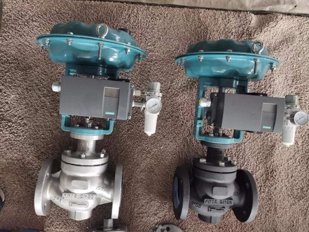
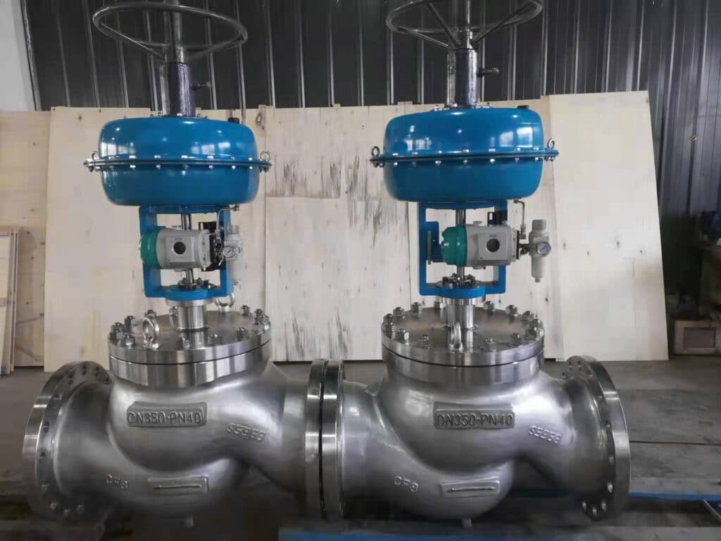
Siemens PS2 positioner integrated with globe-type control valves
This guide expands upon the essential troubleshooting information available in the Siemens PS2 Valve Positioner Troubleshooting PDF, providing detailed insights and SEO optimization for English-speaking professionals in the field.
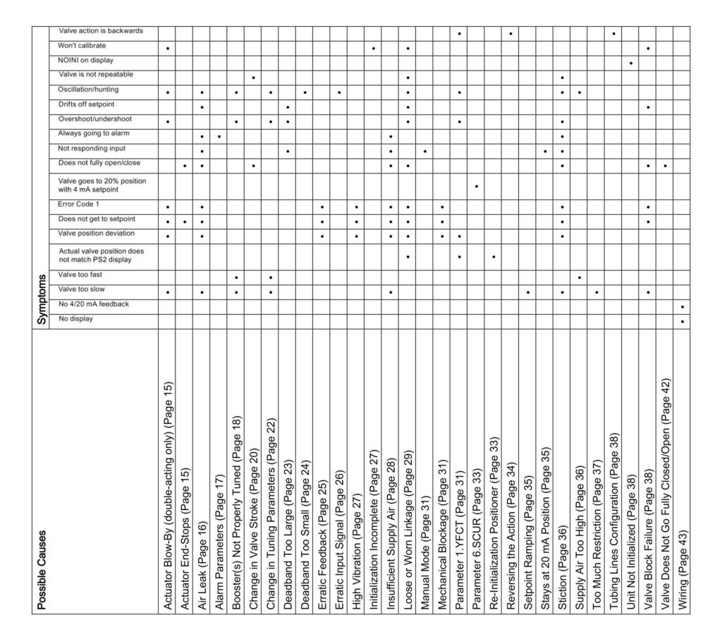
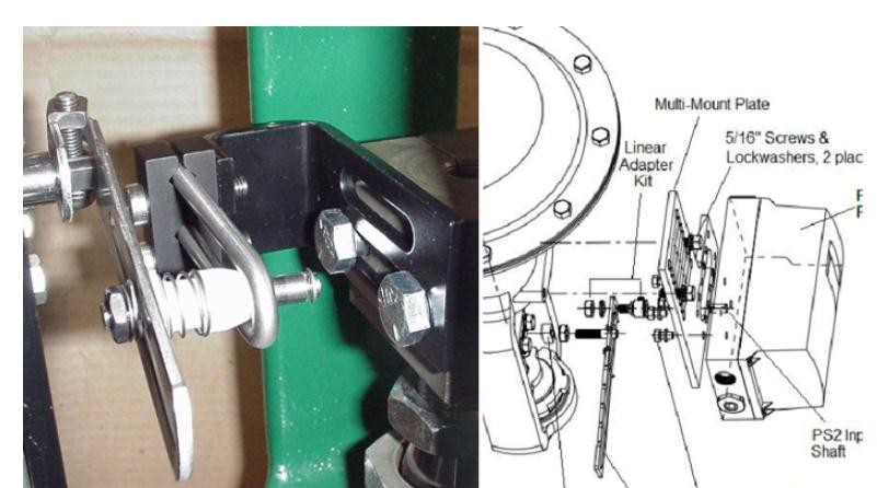
Visual guide for PS2 positioner troubleshooting
Common Siemens PS2 Positioner Issues and Diagnostic Steps
Below are common problems encountered with Siemens PS2 positioners, along with symptoms, potential causes, and troubleshooting steps, incorporating the ps2 diagnosis mode where applicable.
1. Pneumatic Actuator Blow-By (Double-Acting)
Symptoms
- Slow valve action
- Calibration failure
- Valve oscillation or hunting
- Position overshoot/undershoot
- Error code 1
- Inability to reach setpoint
- Valve position deviation
This issue is specific to pneumatic double-acting actuators using both Y1 and Y2 output ports.
Cause: Internal leakage within the actuator, preventing differential pressure build-up necessary for valve movement.
Troubleshooting Steps:
- Observe Exhaust Port: Check for continuous air blow-out from the exhaust port while attempting valve movement.
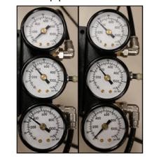
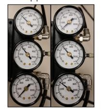
- Pressure Gauge Check: Monitor Y1 and Y2 output pressure gauges. Relatively equal pressure readings indicate blow-by.
- Actuator Inspection: The actuator likely has an internal leak requiring repair.
Further reading on Control Valves Used in Power Stations.
2. Actuator End Stop Misconfiguration
Symptoms
- Valve not fully closing or opening
- Inability to reach setpoint
Cause: Improperly set actuator end stops, leading to excessive valve seating or over-rotation in the open position.
Troubleshooting Steps:
- Manual Review: Consult actuator/valve manuals for correct end-stop settings.
- Manual Mode Operation: Enter PS2 manual mode (press “Operating mode” from Auto once).
- Valve Positioning: Use “Increment” and “Decrement” buttons to move the valve to end-stop positions and assess proper seating.
- End-Stop Adjustment: Adjust actuator end-stops as needed, referring to the actuator’s service manual.
- PS2 Re-initialization: Re-initialize the PS2 positioner after adjustments.
Learn more about Control Valves 101.
3. Air Leak Detection
Symptoms
- Slow valve action
- Valve oscillation or hunting
- Setpoint drift
- Frequent alarms
- No response to input changes
- Valve not fully closing or opening
- Error code 1
- Inability to reach setpoint
- Valve position deviation
Cause: Pneumatic leaks in fittings, air lines, or the actuator itself.
Troubleshooting Steps:
- Parameter Verification (Firmware 5.00.00+): Ensure “PNEUM” parameter is correctly set to “Std” (Standard Valve Block) or “FIP” (Fail In Place Valve Block).
- Leak Test via Diagnosis Mode:
- In Manual or “noini” mode, move the valve to mid-stroke using “Increment/Decrement” buttons.
- Enter PS2 diagnosis mode by pressing and holding all three buttons for 2+ seconds.
- Navigate to “LEAK” diagnostic using “Operating mode” button.
- Initiate leak test by pressing and holding “Increment” button for 5+ seconds. Display will flash “test” and position.
- After one minute, leak rate (%) is displayed. Rate > 1.0% requires correction.
- Exit diagnosis mode by holding “Operating mode” for 5 seconds, then press once to return to Auto mode.
- Physical Leak Check: Inspect pneumatic fittings, air lines, and actuator using leak detection solution or soapy water.
4. Alarm Parameter Configuration
Symptoms
- Continuous alarms
Cause: Incorrect alarm configuration settings.
Troubleshooting Steps:
- AFCT Parameter Check:
- From AUT or MAN mode, press button 1 for 5 seconds to enter parameter mode.
- Navigate to “AFCT” parameter.
- Ensure “AFCT” is set to “OFF”.
- TIM & LIM Parameters: Verify that “TIM” and “LIM” parameters are not set to zero.
5. Booster Tuning Issues
Symptoms
- Slow valve action
- Valve oscillation or hunting
- Position overshoot/undershoot
- Valve action too fast
Cause: Improperly tuned pneumatic volume booster.
Troubleshooting Steps:
- Needle Valve Adjustment: Adjust booster bypass needle valve (clockwise to increase response, counter-clockwise to decrease).
- Initialization after Adjustment: Re-initialize PS2 after any needle valve adjustments.
- “NOINI” Mode Setup: Utilize P-manual mode (“NOINI” flashing) to setup booster BEFORE initialization.
- Manual Valve Movement in “NOINI” Mode: Use push buttons to move valve through stroke in “NOINI” mode for setup. Adjust needle valve until valve stops moving when buttons released at any position.
- Leak Check/Booster Replacement: If issues persist, check for air leaks or consider booster replacement.
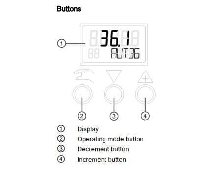
PS2 display showing “NOINI” mode
6. Valve Travel Changes
Symptoms
- Valve position not repeatable
- Valve not fully closing or opening
Potential Causes:
Process Material Build-up
Cause: Process material accumulation on valve and seat, obstructing full closure or opening.
Troubleshooting Steps:
- Manual Mode Operation: Enter PS2 manual mode.
- End-Stop Positioning: Use two-button method to drive valve to both end-stop positions.
- Pressure Gauge Monitoring: Verify PS2 outputs full supply and exhausts pressure in both directions.
- Actuator/Valve Inspection: If PS2 output is correct, check actuator/valve for mechanical binding or valve seat wear.
Valve Seat Wear
Cause: Worn valve seat leading to over-travel and process leaks.
Troubleshooting Steps: (Same as Process Material Build-up)
- Manual Mode Operation
- End-Stop Positioning
- Pressure Gauge Monitoring
- Actuator/Valve Inspection: If PS2 output is correct, check actuator/valve for mechanical binding or valve seat wear.
7. Tuning Parameter Adjustments
Symptoms
- Slow valve action
- Valve oscillation or hunting
- Position overshoot/undershoot
- Valve action too fast
Cause: Incorrect tuning parameters for the application.
Adjustable Tuning Parameters:
- IMPUP & IMPDN (Impulse Length UP/DOWN): Gain adjustment (range 2.0 – 160 ms).
- SSUP & SSDN (Short Step Zone): Integral action (percentage of stroke).
- PRUP & PRDN (Prediction Up/Down): Derivative action (range 1 – 40).
Customizing Tuning Parameters via Diagnosis Mode:
- Enter PS2 Diagnosis Mode: In Auto mode, press and hold all three buttons.
- Navigate Parameters: Use button 1 to cycle through diagnostic parameters. Use button 1 + button 3 to go backward.
- Edit Tuning Value: At desired parameter, hold button 2 until value changes. Use buttons 2 & 3 to adjust.
- Exit Diagnosis Mode: Hold button 1 until display changes. Return to Auto mode if needed.
8. Deadband Too Large
Symptoms
- Setpoint drift
- Position overshoot/undershoot
- No response to small input changes
Cause: Excessive deadband setting, preventing precise positioning.
Troubleshooting Steps:
- Deadband Setting Check:
- Diagnosis Mode for Deadband Value: Enter ps2 diagnosis mode (hold all 3 buttons). Navigate to “DBUP” or “DBDN” to view current deadband.
- Parameter “DEBA” Check: From AUT/MAN mode, enter parameter mode (hold button 1). Navigate to “DEBA”. “Auto” indicates dynamic deadband. Numerical value indicates fixed deadband.
- Reduce Deadband: If needed, decrease fixed deadband value in “DEBA” parameter.
- Process Control Loop Review: Large deadband may compensate for process control loop issues (excessive setpoint changes).
9. Deadband Too Small
Symptoms
- Valve oscillation or hunting
Cause: Insufficient deadband, causing continuous valve adjustments around the setpoint.
Troubleshooting Steps:
- Deadband Setting Check: (Same as Deadband Too Large – check “DEBA” parameter in configuration or “DBUP”/”DBDN” in ps2 diagnosis mode).
- Increase Deadband or Set to “Auto”: Increase fixed deadband value or switch “DEBA” to “Auto” for dynamic adjustment.
10. Erratic Feedback Signal
Symptoms
- Error code 1
- Inability to reach setpoint
- Valve position deviation
Cause: False or unstable feedback signal, while actual valve position is stable.
Troubleshooting Steps:
- Field Wiring and Power Supply Check:
- Verify if jumpy feedback signal is reflected on local display.
- Isolate Field Wiring (If No): Use independent power source to power feedback card directly to isolate wiring issues.
- Erratic Feedback Still Present (If Yes): Proceed to mechanical checks.
- Manual Mode Valve Movement: Enter Manual mode and move valve with buttons.
- Non-Contacting Technology: If erratic feedback corrects with valve movement, consider non-contacting feedback technology.
- Slide Bar Verification: Check slide bar position:
- Rotary: 90°
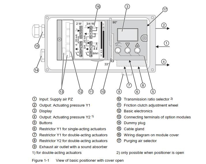
- Linear (≤ 25mm travel): 33°
- Linear (> 25mm travel): 90°
- PS2 Re-initialization: Re-initialize PS2.
11. Erratic Input Signal
Symptoms
- Valve oscillation or hunting
Cause: Unstable or fluctuating input signal from the control system.
Troubleshooting Steps:
- Input Signal Monitoring via Diagnosis Mode:
- Enter ps2 diagnosis mode (hold all 3 buttons).
- Navigate to “mA” diagnostic parameter.
- Observe “mA” reading against valve behavior.
- Current Meter in Loop: Alternatively, use a current meter in series with the 4-20 mA loop.
- Control System Investigation: If “mA” reading fluctuates with valve movement, investigate control system/loop tuning.
12. High Vibration Environment
Symptoms
- Error code 1
- Inability to reach setpoint
- Valve position deviation
Cause: Excessive vibration affecting positioner operation.
Troubleshooting Steps:
- Vibration Specification Check: Verify vibration levels against PS2 specifications.
- Vibration Reduction: If possible, reduce vibration at the installation point.
- Non-Contacting Technology: Consider non-contacting positioner technology for high vibration environments.
13. Initialization Incomplete
Symptoms
- Calibration failure
| Fault Profile (Symptoms) | Possible Cause(s) | Corrective Measures |
|---|---|---|
| Positioner remains in “RUN 1” | • Waiting time insufficient.• Loose Linkage.• Air supply issues.• Valve Block Failure | • Ensure 2-minute waiting time. Start initialization mid-stroke.• Inspect Linkage.• Check Air Supply.• Inspect Valve Block. |
| Positioner remains in “RUN 2” | • Incorrect transmission ratio/stroke parameter.• Lever stroke misconfiguration.• Valve Block issue | • Re-initialize PS2.• Verify parameter “2. YAGL” and stroke settings.• Inspect Valve Block. |
| Positioner remains in “RUN 3” | • Actuator travel time too long.• Air Leak.• Non-active zone in valve stroke | • Open restrictor, increase air supply.• Check for Air Leak.• Address non-active zone/Valve Block. |
| Positioner remains in “RUN 4” | • Air Leak.• Booster Tuning.• Loose Linkage | • Check for Air Leak.• Tune Booster properly.• Inspect Linkage. |
| Positioner remains in “RUN5” (> 7 min) | • Loose Linkage.• Booster Tuning.• Air Leak | • Secure couplings & linkages.• Tune Booster properly.• Check for Air Leak. |

14. Insufficient Supply Air
Symptoms
- Slow valve action
- Frequent alarms
- No response to input changes
- Valve not fully closing or opening
- Error code 1
- Inability to reach setpoint
- Valve position deviation
Cause: Inadequate air supply pressure.
Troubleshooting Steps:
- Supply Pressure Adjustment: Adjust supply pressure to actuator specifications (within PS2 max 100 psi limit).
- PS2 Re-initialization: Re-initialize PS2 after pressure adjustments.
15. Loose or Worn Linkage
Symptoms
- Valve oscillation or hunting
- Calibration failure
- Valve position not repeatable
- Setpoint drift
- Position overshoot/undershoot
- Valve not fully closing or opening
- Error code 1
- Inability to reach setpoint
- Valve position deviation
- Slow valve action
Cause: Loose or worn mechanical linkage between positioner and actuator.
Troubleshooting Steps:
- Slip Clutch Check: In Manual or “NOINI” mode, move slip clutch. It should click and not rotate freely.
- Visual Linkage Inspection: In Manual or “NOINI” mode, move valve back and forth and observe:
- Rotary: Actuator shaft, Positioner coupling, Positioner input shaft.
- Linear: Actuator shaft, Actuator stem coupling, Feedback pin, Feedback arm, Positioner input shaft.
- Unison Movement: Verify all components move together without slippage or looseness.
16. Manual Mode Engagement
Symptoms
- No response to input signal
Cause: Positioner unintentionally in Manual mode.
Troubleshooting Steps:
- Mode Display Check: Verify bottom display shows “AUTxx” (Automatic mode) not “MANxx” (Manual mode).
- Exit Manual Mode: Press “Operating mode” button once to switch to Automatic mode.
17. Mechanical Blockage
Symptoms
- Error code 1
- Inability to reach setpoint
- Valve position deviation
Cause: Mechanical obstruction preventing valve movement.
Troubleshooting Steps:
- Output Pressure Monitoring: Check output pressure gauges during deviation.
- Full Supply Pressure Output: If output pressure equals supply pressure, mechanical blockage is likely in actuator/valve.
- Insufficient Output Pressure: If output pressure is low, check for air leaks.
- Exhaust Blockage: If output pressure cannot exhaust, check exhaust port blockage or replace piezo block.
- Deadband Check: Consider if deadband is set too large.
18. Parameter 1.YFCT (Feedback Type)
Symptoms
- Valve oscillation or hunting
- Backward valve action
- Position overshoot/undershoot
- Valve position deviation
- Displayed position mismatch
Cause: Incorrect feedback type parameter setting.
Parameter Options:
- WAY/ -WAY: Linear actuators with feedback arm.
- TURN/ -TURN: Rotary actuators with direct coupling.
- FWAY/ -FWAY: Linear actuators with pin on actuator spindle.
- LWAY/ -LWAY: External linear potentiometer.
- ncSt/ -ncSt, ncSL/ -ncSL, ncSLL/ -ncLL: NCS sensor types.
Troubleshooting Steps:
- Parameter 1 Verification: Ensure Parameter 1.YFCT is correctly set for actuator type (linear/rotary) and feedback mechanism. “Inverted” options (- prefix) are for reversed action.
19. Parameter 6.SCUR (Setpoint Current)
Symptoms
- Valve goes to 20% at 4mA setpoint
Cause: Incorrect setpoint current parameter.
Troubleshooting Steps:
- Parameter 6.SCUR Check:
- From AUT/MAN mode, enter parameter mode (hold button 1).
- Navigate to “SCUR” parameter.
- Ensure “SCUR” is set to “4 mA” (default).
20. Re-Initialization Requirement
Symptoms
- Actual valve position mismatch with PS2 display
Cause: Positioner needs re-initialization after parameter changes or mechanical adjustments.
Troubleshooting Steps:
- Perform PS2 Re-initialization: Follow the PS2 initialization procedure.
21. Action Reversal
Symptoms
- Backward valve action
Methods to Reverse Action:
No Re-initialization (Action & Display Reversal):
- SDIR Parameter (Action Reversal): Change “SDIR” parameter (“riSE” to “FALL” or vice versa) to reverse physical action.
- YDIR Parameter (Display & Feedback Reversal): Change “YDIR” parameter (“riSE” to “FALL” or vice versa) to reverse display and feedback.
Re-initialization Procedure (Firmware 5.00.00+):
- Parameter 1 Inverse Function: Change Parameter 1.YFCT to its inverse (e.g., “turn” to “-turn”).
- PS2 Re-initialization: Re-initialize PS2 after Parameter 1 change.
22. Setpoint Ramping Adjustment
Symptoms
- Slow valve action
Cause: Setpoint ramp parameters slowing down valve response.
Troubleshooting Steps:
- TSUP & TSDO Parameter Check:
- From MAN/AUT mode, enter configuration menu (hold button 1).
- Navigate to “TSUP” and “TSDO” parameters.
- Set “TSUP” and “TSDO” to zero for fastest response.
23. Stays at 20 mA Position
Symptoms
- No response to input changes
Cause: Power supply issues or board malfunction.
Troubleshooting Steps:
- Input Signal “mA” Diagnostic Check:
- Enter ps2 diagnosis mode (hold all 3 buttons).
- Navigate to “mA” diagnostic parameter.
- Check “mA” reading. Fixed ≈ 22.0 mA indicates power issue.
- Power Supply Verification: Ensure regulated current source for 2-wire loop power. Voltage source can damage PS2.
- Circuit Board Replacement: Resolve power issue and replace PS2 circuit board if damaged.
- Factory Reset (If mA changes):
- Enter parameter mode (hold button 1).
- Navigate to “PRST” parameter.
- Hold button 2 until display shows “OCAY” for factory reset.
- Configuration & Re-initialization: Reconfigure parameters and re-initialize PS2 after reset.
24. Stiction Issues
Symptoms
- Slow valve action
- Valve oscillation or hunting
- Valve position not repeatable
- Position overshoot/undershoot
- Frequent alarms
- No response to input changes
- Valve not fully closing or opening
- Error code 1
- Inability to reach setpoint
- Valve position deviation
Cause: Excessive friction (stiction) in valve assembly hindering smooth movement.
Troubleshooting Steps:
- Manual Mode Small Movement Test: In Manual mode, attempt to move valve in small increments (e.g., 0.2%).
- Stiction Quantification: Determine minimum achievable movement increment. Large increment indicates high stiction.
- Deadband Adjustment: Set Deadband parameter “DEBA” to “Auto” to reduce oscillations caused by stiction.
Explore Frequently Asked Questions About Globe Valves for related valve mechanics.
25. Supply Air Pressure Too High
Symptoms
- Valve oscillation or hunting
- Valve action too fast
Cause: Excessive air supply pressure.
Troubleshooting Steps:
- Supply Pressure Adjustment: Reduce supply pressure to actuator specifications.
- PS2 Re-initialization: Re-initialize PS2 after pressure adjustments.
- Travel Time Check via Diagnosis Mode:
- Enter ps2 diagnosis mode (hold all 3 buttons).
- Navigate to “TUP” and “TDOWN” parameters to check travel times.
- Flow Restrictor Adjustment: If travel times < 1 second, adjust built-in flow restrictors (clockwise to restrict flow). Adjust during “RUN 3” initialization phase when times are flashing.
26. Excessive Flow Restriction
Symptoms
- Slow valve action
Cause: Restrictor screws excessively closed.
Troubleshooting Steps:
- Restrictor Screw Inspection: Verify restrictor screws are fully open (factory position).
- Restrictor Adjustment: Open restrictors by turning counter-clockwise to factory position.
- PS2 Re-initialization: Re-initialize PS2 after restrictor adjustments.
27. Incorrect Tubing Configuration
Symptoms
- Backward valve action
Cause: Tubing lines connected incorrectly.
Troubleshooting Steps:
- Tubing Configuration Verification: Check tubing connections against PS2 and actuator documentation.
28. Unit Not Initialized
Symptoms
- “NOINI” displayed
Cause: Positioner not yet initialized.
Troubleshooting Steps:
- Perform PS2 Initialization: Follow the PS2 initialization procedure.
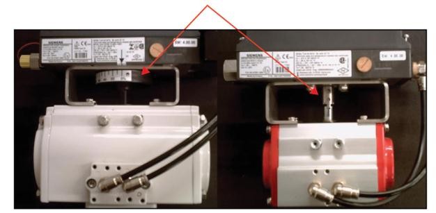
Example application with DN350 pressure control valve
29. Valve Block Failure
Symptoms
- Slow valve action
- Calibration failure
- Setpoint drift
- Valve not fully closing or opening
- Error code 1
- Inability to reach setpoint
Cause: Valve block malfunction, often due to contaminated air or overpressure.
Troubleshooting Steps:
- Air Quality Check: Verify air quality and consider coalescent filter installation.
- Supply Pressure Check: Ensure supply pressure is within PS2 and actuator limits.
- Valve Block Testing (NOINI Mode):
- Activate “NOINI” mode (Parameter 4.INITA to “no”).
- Use two-button method to simulate valve movement.
- Observe pressure gauge behavior on output ports for single/double-acting actuators.
- Pressure Holding Test (Mid-stroke): In “NOINI” mode, move valve to mid-stroke. Check if pressure holds when buttons released. No hold indicates valve block issue or leaks.
- Exhaust Test: Verify proper exhaust from output ports during movement.
- Pipe Plug Test: Isolate valve block by plugging output ports and test pressure output.
- Valve Block Replacement: If valve block fails tests, replace it.
Understand Globe Valve Characteristics for related valve performance factors.
30. Valve Not Fully Closing/Opening
Symptoms
- Valve not fully closing or opening
Cause: Configuration parameter preventing tight shut-off.
Troubleshooting Steps:
- YCLS Parameter Adjustment:
- From AUT/MAN mode, enter parameter mode (hold button 1).
- Navigate to “YCLS” parameter.
- Set “YCLS” to “Up do” (Tight Closing Up and Down).
- Input Signal Verification via Diagnosis Mode:
- Enter ps2 diagnosis mode (hold all 3 buttons).
- Navigate to “mA” diagnostic parameter.
- Verify ≈ 4 mA input signal for closed position and 20mA for open.
31. Wiring Issues
Symptoms
- No display
- No 4-20mA feedback
Cause: Incorrect or faulty wiring.
Troubleshooting Steps:
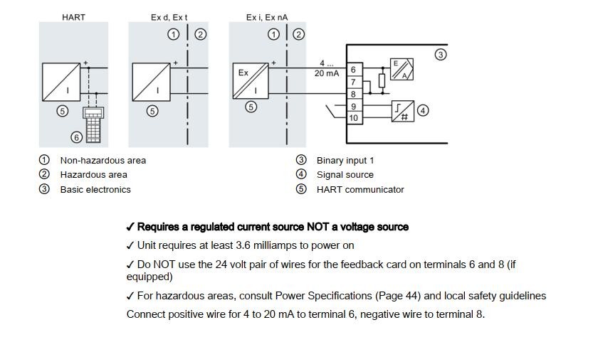
- Wiring Inspection: Check wiring against wiring diagrams for 2-wire connection and 4-20mA feedback module (if applicable).
2-Wire Connection Wiring
Learn about Different Types of Control Valves.
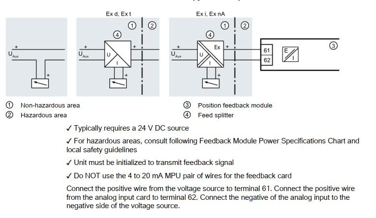
4 to 20 mA Feedback Module Wiring
Troubleshooting Case Studies: SIPART PS2 in Action
Case 1: Control Valve Not Fully Closed
Solution: Enable tight shutoff function by adjusting parameters 39YCLS, 40YCD, and 41YCU to maximize valve closure for leak prevention in processes with plug wear or high differential pressure.
Case 2: Non-Ideal Control Valve Flow Curve
Solution: Utilize parameter 12SFCT to adjust flow characteristics. Choose from built-in curves or user-defined options to match process requirements beyond the valve’s inherent linear characteristic.
Understand Control Valve Flow Characteristics.
Case 3: Incorrect Control Valve Action Direction
Solution: Correct parameters 7SDIR (setpoint direction) and 38YDIR (travel direction display) by comparing actual valve action to control room signals. Careful rotary valve direction assessment is critical to prevent operational errors.
Case 4: Initialization Stops at RUN5
Solution: Investigate mechanical installation of positioner, actuator, and feedback components. Correct any misalignments or issues and re-initialize to shorten initialization time.
Find a Reliable Triple Eccentric Butterfly Valve Supplier.
Case 5: Initialization Stops at RUN3
Solution: Address prolonged actuator positioning time by fully opening restrictors, increasing air pressure (PZ), or implementing a booster to enhance actuator force and reduce switching time.
Case 6: Initialization Stops at RUN2
Solution: Adjust feedback shaft rotation angle in parameter 2YAGL. Change from 33° to 90° and re-initialize. Manual actuator stroke adjustment can also bypass automatic initialization issues in RUN2.
Case 7: Positioner Puffing Sound and Valve Vibration
Solution: Detect air tubing leaks using soapy water, specifically checking positioner outlet air pipelines and actuator air source connections.
Source Best Pneumatic On-Off Globe Control Valves for robust valve solutions.
Case 8: Control Valve Maintenance and Accuracy Problems
Solution: Re-initialize PS2 after maintenance due to potential changes in positioner, valve stem, and feedback components. Follow the five-step automatic initialization process for proper matching and control.
Discover Top Industrial Valve Manufacturers.
Case 9: PS2 Smart Positioner Malfunction
Solution: Oil coating on the mainboard caused erratic behavior. Cleaning the circuit board, switching to external exhaust, restoring settings, and re-initializing resolved the issue.
Case 10: Failure Due to Water in Compressed Air
Solution: Water damage to the piezoelectric valve. Isolating the mainboard and piezoelectric valve, cleaning the button structure with alcohol, or replacing the piezoelectric valve or mainboard are potential fixes.
Explore V-Port Ball Valves vs. Globe Control Valves for valve selection insights.
By understanding these common issues and effectively utilizing the ps2 diagnosis mode, field engineers can significantly improve their troubleshooting efficiency and maintain optimal performance of control valves equipped with Siemens SIPART PS2 positioners.